
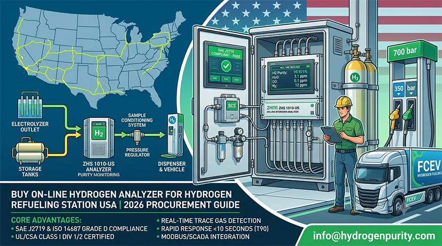
A hydrogen leak can develop at a compressor seal, valve stem, flange, analyser connection or recovery skid long before operators notice a change in process pressure. Because hydrogen is colourless and odourless, personnel cannot reliably detect a release without suitable instrumentation.
A hydrogen leak detection system for production plants should detect credible releases early, initiate clearly defined protective actions and remain dependable under actual operating conditions. Installing detectors alone is not enough: coverage, sensor selection, ventilation, alarm logic and maintenance must work together.
This guide explains the common causes of poor detection performance and the practical steps plant operators, engineering teams and procurement specialists can take to address them.
What Should a Hydrogen Leak Detection System Do?
A fixed hydrogen detection system continuously monitors selected locations for hydrogen accumulation or release. Depending on the plant’s risk assessment, it may activate local warnings, notify the control room, increase ventilation, isolate equipment or initiate a controlled shutdown.
A complete installation typically includes:
- Hydrogen-compatible sensors and transmitters.
- A gas detection controller, safety system or appropriately designed control-system interface.
- Audible and visual alarms.
- Ventilation, isolation and shutdown interfaces where required.
- Power, communications and fault monitoring.
- Calibration access, maintenance procedures and inspection records.
Gas detection is a protective layer, not a substitute for leak-tight equipment, suitable ventilation, hazardous-area electrical design or safe operating procedures.
Hydrogen has a commonly cited lower flammable limit, or LFL, of approximately 4% by volume in air under ambient reference conditions. Actual flammability behaviour depends on temperature, pressure and gas composition. Detector readings and alarm settings must therefore use clearly defined units and reference conditions.
Common Problems—and Why They Occur
| Operational problem | Likely cause | Practical response |
|---|---|---|
| A known leak does not trigger an alarm promptly | Poor detector location, airflow carrying gas away, or excessive sampling delay | Reassess release scenarios, airflow and total system response time |
| Frequent nuisance alarms | Cross-sensitivity, contamination, condensation, electrical interference or genuine intermittent releases | Investigate event trends and environmental conditions before changing settings |
| Sensor passes calibration but misses releases | Calibration confirms sensor response, not coverage | Validate detector placement separately from calibration |
| Readings drift or become sluggish | Sensor ageing, poisoning, blocked inlet or unsuitable environmental exposure | Inspect, challenge-test and replace components according to approved procedures |
| Alarms occur but operators respond inconsistently | Unclear alarm priorities or incomplete cause-and-effect documentation | Define, test and train the response to each alarm and fault state |
| Detection becomes unavailable during maintenance | No bypass procedure, inadequate redundancy or missing compensating measures | Introduce controlled impairment management and restoration checks |
1. Start with Credible Leak Scenarios, Not Detector Counts
One of the most common design mistakes is specifying a detector quantity before identifying where hydrogen could escape and how it would move.
A practical assessment should review:
- Compressor seals, packing and associated connections.
- Valve stems, flanges, regulators and instrument fittings.
- Electrolyser gas handling and separation equipment.
- Pressure swing adsorption systems and hydrogen purification skids.
- Membrane recovery units and off-gas treatment equipment.
- Storage manifolds, cylinder connections and transfer points.
- Sampling systems, purge connections and maintenance interfaces.
- Enclosed equipment packages and poorly ventilated roof spaces.
Include normal operation, start-up, shutdown, purging, maintenance and foreseeable equipment failures.
Why hydrogen behaviour complicates placement
Hydrogen is highly buoyant in air, but a pressurised release initially behaves as a directional jet. Its path depends on release pressure, opening geometry, nearby equipment and ventilation. Detectors mounted only at the ceiling may miss a release carried through another part of the building or diluted before reaching the sensor.
Use release assessment and airflow review to establish coverage. Complex enclosed installations may warrant dispersion modelling or other engineering studies.
There is no universal detector spacing that guarantees coverage for every hydrogen facility.
2. Choose Sensor Technology for the Actual Environment
Selecting a fixed hydrogen gas detection system for industrial plants requires more than comparing measurement ranges. The sensor must work reliably in the expected gas mixture, oxygen level, temperature, humidity and contamination environment.
| Sensor technology | Potential application | Important limitations |
|---|---|---|
| Catalytic bead | Combustible gas detection in oxygen-containing atmospheres | Requires sufficient oxygen; may be affected by poisons and inhibitors; responds to multiple combustible gases |
| Electrochemical | Low-concentration hydrogen monitoring with suitably specified sensors | Range, service life, cross-sensitivity and environmental limits vary by model |
| Semiconductor or metal oxide | Hydrogen monitoring where validated for the application | Humidity, temperature and other gases may influence response |
| Thermal conductivity | Selected hydrogen measurement duties, particularly at higher concentrations | Response depends on background gas composition; suitability for low-level leak detection must be demonstrated |
| Ultrasonic acoustic detection | Supplementary detection of pressurised gas releases | Detects leak-generated sound rather than hydrogen concentration; coverage depends on pressure, leak characteristics and background noise |
Conventional infrared combustible-gas detectors designed for hydrocarbons generally do not detect hydrogen. Do not assume that an existing methane detector provides hydrogen coverage.
Questions to ask before selecting a detector
Require suppliers to document:
- Hydrogen-specific measurement range and response characteristics.
- Accuracy and repeatability over the intended operating range.
- Relevant cross-sensitivities.
- Oxygen requirements, where applicable.
- Temperature, humidity and ingress-protection limits.
- Expected sensor life and replacement criteria.
- Hazardous-location certification for the installation.
- Calibration methods and approved test gases.
- Fault outputs and behaviour during sensor failure or communications loss.
Explosion-protection certification and gas-measurement performance are separate considerations. A detector approved for a hazardous location is not automatically suitable for every hydrogen detection duty.
3. Place Detectors Where Gas Can Reach Them
Effective hydrogen leak detector installation for compressor rooms should consider both likely leak sources and potential accumulation zones.
Useful locations may include:
- Above likely release points, where release behaviour and ventilation support that position.
- Within enclosed compressor or purification packages.
- At high-level pockets beneath roofs, canopies or structural obstructions.
- Along credible gas migration paths identified by engineering assessment.
- Near relevant ventilation extraction points, where representative detection is demonstrated.
Avoid relying on locations selected solely because they are easy to wire or service.
Check ventilation under abnormal conditions
Review airflow with:
- Doors open and closed.
- Normal and standby fans operating.
- A ventilation fan unavailable.
- Heating or cooling systems in different operating modes.
- Temporary screens, scaffolding or equipment obstructing circulation.
Ventilation can reduce accumulation, but it can also divert hydrogen away from a detector. A detector placed directly in a clean supply-air stream may provide misleading reassurance.
Sampling systems require additional care. Tubing length, sample flow, filters and conditioning components can delay detection. Evaluate the complete response time from gas entering the sampling point to the protective action being completed.
4. Define Alarm Levels and Protective Actions Together
An alarm threshold is useful only when the plant has a clear response to it.
Plants often use staged alarms expressed as a percentage of the LFL. For illustration, using an LFL reference of 4% hydrogen by volume:
- 10% LFL corresponds to 0.4% hydrogen by volume, or 4,000 ppm.
- 25% LFL corresponds to 1% hydrogen by volume, or 10,000 ppm.
These conversions are not universal alarm-setting recommendations. Required settings depend on applicable codes, the authority having jurisdiction, the process hazard assessment and detector performance.
Build a documented cause-and-effect matrix
For each alarm or fault, identify:
- Which audible and visual warnings activate.
- Which messages appear in the control room.
- Whether ventilation changes are initiated.
- Whether hydrogen supply is isolated.
- Whether equipment stops or enters a controlled shutdown sequence.
- Whether evacuation or access restrictions apply.
- Who may reset the system and under what conditions.
Protective actions must not introduce a new hazard. For example, stopping process equipment without maintaining required purge or cooling functions may create an unsafe condition.
Where detection is credited as a safety instrumented function, address the relevant functional safety lifecycle requirements, such as those in IEC 61511. A safety integrity level cannot be established merely by selecting a transmitter with a SIL-related certificate.
5. Investigate Nuisance Alarms Without Weakening Protection
Repeated alarms can erode operator confidence. However, raising thresholds or adding time delays without technical review may conceal a real release.
Investigate systematically:
- Treat the alarm as genuine initially. Follow the plant’s emergency response procedure.
- Review process history. Compare the event with compressor starts, purges, valve movements and maintenance work.
- Check environmental influences. Consider condensation, cleaning chemicals, humidity changes and nearby work.
- Inspect the detector. Look for contamination, blocked protection elements or damaged wiring.
- Verify response with approved test gas.
- Review coverage and sensor suitability. Relocation or technology changes may be necessary.
Portable instruments can support a trained investigation, but personnel should not enter a potentially hazardous atmosphere merely to confirm a fixed alarm.
6. Establish Testing That Covers the Whole System
A hydrogen gas detection system calibration and maintenance service should distinguish between sensor checks and verification of the complete protective function.
Bump testing
A bump test exposes the sensor to an appropriate gas to verify response and, where included in the procedure, alarm operation. It does not establish measurement accuracy across the operating range.
Calibration
Calibration checks and, where necessary, adjusts measurement response using suitable reference gas and the manufacturer’s procedure.
Functional and proof testing
An end-to-end functional test checks the path from detection to alarms and specified outputs. Where a safety instrumented function is involved, proof testing must follow the defined procedure and provide the required test coverage.
Set intervals using:
- Manufacturer instructions.
- Applicable regulatory or code requirements.
- Exposure to contamination or harsh conditions.
- Operating experience and failure history.
- Risk assessment and functional safety calculations, where relevant.
There is no single maintenance interval appropriate for every hydrogen installation.
Record as-found and as-left results, gas cylinder details, sensor replacements, output checks and restoration of bypassed functions.
7. Address European and North American Compliance Correctly
Compliance depends on jurisdiction, adopted code editions, facility configuration and hydrogen inventory. A supplier’s general claim of “ATEX compliant” or “NFPA compliant” does not establish compliance for the complete installation.
European considerations
Relevant frameworks may include:
- ATEX Directive 2014/34/EU: Equipment and protective systems intended for potentially explosive atmospheres.
- Directive 1999/92/EC: Workplace requirements for protecting workers exposed to explosive atmospheres.
- EN/IEC 60079 series: Relevant requirements and guidance for hazardous-area classification, equipment selection, installation, inspection and gas detection.
- ISO 26142: Hydrogen detection apparatus requirements for stationary applications.
- National fire, occupational safety and building requirements.
IECEx certification may support equipment assessment, but it does not replace applicable EU legal obligations.
United States and Canadian considerations
Depending on jurisdiction and adoption, relevant documents may include:
- NFPA 2, Hydrogen Technologies Code.
- NFPA 55, Compressed Gases and Cryogenic Fluids Code.
- NFPA 70, National Electrical Code, for US electrical installations.
- Applicable OSHA requirements in the United States.
- The Canadian Electrical Code and applicable provincial or territorial requirements.
- Local fire and building codes and authority-having-jurisdiction requirements.
OSHA process safety management and other major-hazard obligations require an applicability assessment; they do not automatically apply to every hydrogen installation.
Always verify current local adoption and project-specific requirements rather than assuming the latest published edition governs the site.
Procurement Checklist: Specify Performance, Not Just Hardware
When requesting a hydrogen leak detection system for production plants, provide vendors with a common technical basis so proposals can be compared meaningfully.
Include:
- Process description, hydrogen composition and operating pressures.
- Credible release locations and operating scenarios.
- Layout drawings, ventilation information and hazardous-area classification.
- Required detection range and system response time.
- Environmental conditions and potential interfering gases.
- Alarm, fault and shutdown requirements.
- Power availability and communications architecture.
- Certification and documentation requirements.
- Commissioning, training and maintenance scope.
- Spare parts availability and lifecycle support.
Require a documented coverage rationale. Neither the lowest detector count nor the highest detector count proves that a design is effective.
A Practical Route to More Reliable Hydrogen Detection
Start with a gap assessment of the existing installation: compare credible release points with detector locations, confirm hydrogen-specific sensor suitability, and test whether alarms produce the intended response.
Prioritise these actions:
- Correct uncovered release and accumulation scenarios.
- Replace unsuitable or poorly performing sensors.
- Validate ventilation and total detection-to-action response time.
- Formalise alarm response and impairment procedures.
- Maintain traceable calibration and functional test records.
- Reassess coverage after process, equipment or building changes.
The most dependable hydrogen leak detection system is one whose performance can be demonstrated—from the release reaching the sensor to the plant taking the correct protective action.









Contact Form