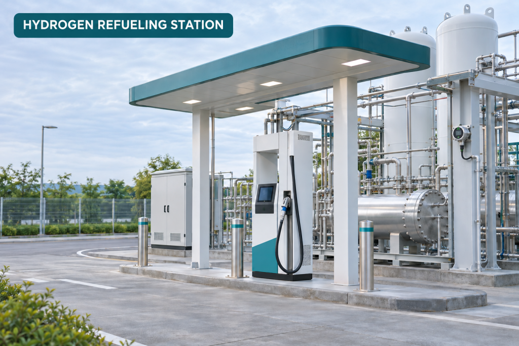
Hydrogen refueling stations bring together storage, compression, dispensing, vehicle connections, and control equipment. A hydrogen leak detection plan should be designed around the station layout, likely release points, ventilation, operating conditions, and the response expected from operators and control systems.
This solution overview helps station owners, EPC contractors, equipment integrators, and operations teams scope a hydrogen gas detection system. Final detector locations, quantities, alarm logic, interfaces, and equipment selection require project-specific information and qualified engineering review.
Where hydrogen leak detection supports station safety
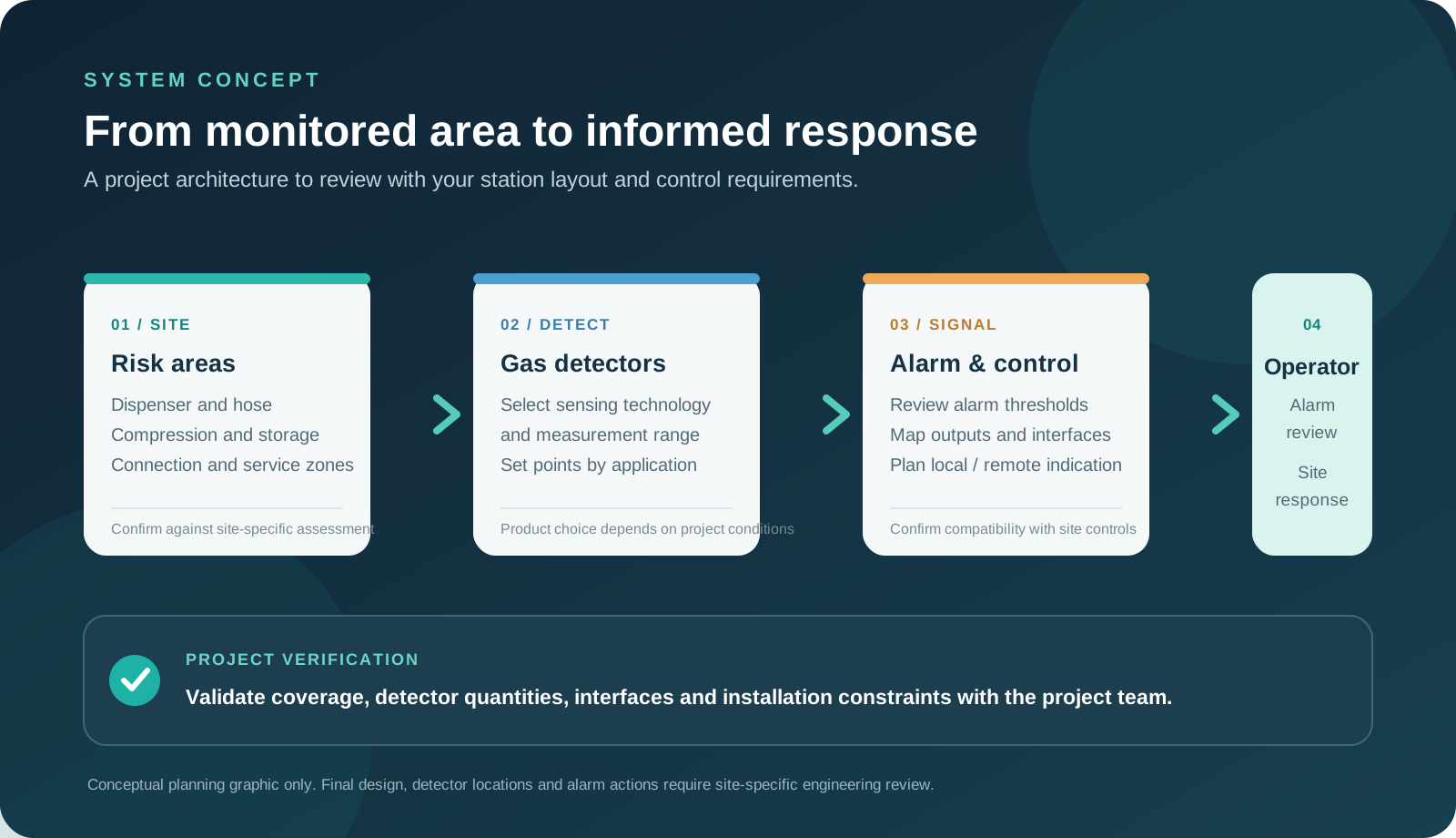
During an initial site review, teams can assess areas where hydrogen may be stored, compressed, transferred, or dispensed. Candidate areas may include:
- Hydrogen storage vessels, supply interfaces, and manifolds.
- Compressors, valves, regulators, flanges, and piping connections.
- Dispenser equipment and vehicle connection areas.
- Equipment enclosures, process rooms, and ventilation outlets.
- Additional locations identified by the station risk assessment.
Detector placement note: final positions should reflect the station design, likely leak sources, gas movement, ventilation, equipment geometry, maintenance access, applicable local requirements, and review by a qualified engineer. A generic layout is only a starting point and does not replace project engineering.
How the detection and alarm system works
- Detect: Hydrogen detectors monitor selected locations and provide signals within their specified operating conditions.
- Process: A compatible gas detection controller receives detector signals and evaluates configured alarm states.
- Alert: Local indicators and audible or visual alarms can notify personnel. Remote notification or relay-driven actions are included only when specified in the project scope.
- Integrate: Supported outputs may connect to a station PLC, SCADA, or another control interface after protocol, wiring, and compatibility review.
ILLUSTRATIVE SYSTEM FLOW
Gas detection is one layer of a broader safety design. It does not by itself replace ventilation, isolation, shutdown logic, operating procedures, or other safeguards defined by the project. Automatic equipment shutdown or valve closure should not be assumed unless it is explicitly engineered, supplied, and commissioned as part of the agreed system.
System components and configuration review
Hydrogen detectors
Detector type, sensing method, range, outputs, environmental limits, and approvals should match the monitored area and station conditions. The NA1000AW Online Hydrogen Detector is documented for indoor industrial ambient-air monitoring by natural diffusion, with local indication and 4–20 mA, RS-485, and relay outputs. Confirm the supplied sensor type, site classification, certificate scope, and compatibility for the intended installation.
Gas detection controller
The RD3000E Gas Leakage Detection Alarm Controller is documented for 1–16 compatible detector channels using supported 4–20 mA or RS-485 inputs. Channel allocation, signal wiring, protocol, alarm setpoints, relay loads, and host-system integration must be checked against the selected detectors and site design.
Alarms, communications, and accessories
Audible or visual alarm devices, relays, network interfaces, mounting hardware, cable, and enclosures should be included only where they are confirmed for the selected equipment and project scope. Agree the alarm response, signal mapping, power arrangement, and integration responsibilities before procurement.
Detector placement designed around your station
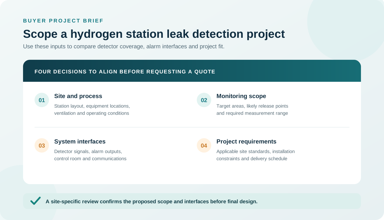
Detector placement should account for potential release points, gas movement, ventilation patterns, equipment geometry, maintenance access, and local requirements. To begin a review, provide a site layout, equipment list, ventilation information, available hazardous-area classification, and the alarm or control interfaces required by the station.
NEED HELP WITH DETECTOR LOCATIONS?
Start with a review of your station layout
Share available drawings, ventilation details, and monitoring points to discuss the next engineering questions.
From site review to commissioning support
- Share project details, drawings, station location, and monitoring objectives.
- Review monitored areas, detector quantity, mounting, signal, alarm, and interface needs.
- Check the proposed equipment configuration against application and site requirements.
- Coordinate supply, installation guidance, and commissioning support as agreed for the project.
Engineering support and product verification
Before purchase, review the data sheets, applicable certificates for the exact supplied model, environmental limits, supported detector-controller combinations, and the integration responsibilities agreed for the project. Share the relevant site and process information so the proposed scope can be checked against your requirements. No detector layout, performance, certification, or project outcome is implied until confirmed for the selected equipment and installation.
Discuss your hydrogen station monitoring requirements
For an initial project review, share the station type and location, project stage, monitored areas, detector models or target gases, interface requirements, and available drawings. The team can review the information and advise on suitable next steps.
Request a Project Review or email [email protected].
Frequently asked questions
Where should hydrogen detectors be installed at a refueling station?
Locations depend on the station layout, likely release points, ventilation, equipment configuration, and applicable local requirements. A project review should confirm final locations.
Can the system connect to a station PLC or SCADA?
Integration depends on the selected controller, available interfaces, protocol, and station control design. Share the required interface for compatibility review.
What information is needed for a project quotation?
A site layout, monitored areas, equipment list, project location, required interfaces, project stage, and schedule help prepare a relevant proposal.
Does the detection system replace other hydrogen safety measures?
No. Gas detection is one part of a broader safety design that may also include ventilation, isolation, shutdown logic, procedures, and other safeguards determined by the project.
Can detector quantities be recommended before drawings are available?
An initial concept can be discussed, but final quantities and positions require sufficient site information and engineering review.